-
parameter analyzer
FE Loop Tracer
A P-E loop for a device is a plot of bound charge or polarization (P) developed against the field (E) applied to that device at a given frequency. We can confirm the ferroelectricity nature of a sample from the saturated P-E loop. The Precision Premier II is an advanced tester that has a large test envelope in terms of frequency response, voltage range and accuracy. It has a fast hysteresis frequency rating of 250KHz at +/-10 V built-in to the system. The Premier II tester makes testing of thin films and bulk ceramics a fast and simple process. Our P-E loop tracer system executes P-E hysteresis loop, leakage current ( I-V curve), and C-V measurements without changing sample connections. The Precision Premier II is offered in a ±10V, 30V, 100V, 200V, and 500V built-in drive volt option. Our system is expanded to 4 kV with the addition of a high voltage interface and amplifier. It includes Vision Data Acquisition and Management Software.
The details of measurement capability are shown below :| Voltage range with an external amplifier and high voltage interface | 4 kV |
| Minimum area resolution | 0.08 μm¬2 |
| Maximum area resolution | 52.6 cm2 |
| Maximum hysteresis frequency | 250 kHz @ 10 V / 50 kHz @ 200 V / 2 kHz @ 500 V |
| Minimum hysteresis frequency | 0.03 Hz |
| Minimum leakage current | 1 pA |
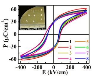
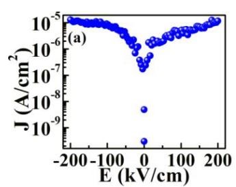
Figure 1(a) P-E hysteresis loops and, (b) leakage current ( J-E ) measurementsof large area (2x2 inch) PZT thin film.
Impedance Analyzer
The 4294A precision impedance analyzer is an integrated solution for efficient impedance measurement and analysis of components and circuits. The Agilent 4294A employs a stateof-the-art auto-balancing-bridge technique in a four-terminal-pair (4TP) measurement configuration. Meticulous circuit design against distortion and instability resulted in a highly accurate and stable measurement system for a wide impedance range.A wide impedance range is required to accurately measure both resonant and anti-resonant impedance of crystal/ceramic resonators. With the trend toward lower power consumption and compact equipment, inductors and capacitors are becoming smaller with lower loss. The efficiency improvement in power conversion for switching power supply applications is an example. These applications require low-loss inductors and capacitors.The dynamic range of the 4294A in terms of impedance is more than 200 dB. When compared to that of a general network analyzer with a directional bridge, at 80 dB, it is clear, the 4294A has an extremely broad impedance-measurement range.It can measure impedance of two terminal components such as capacitors, inductors, ferrite beads, resistors, transformers, crystal/ceramic resonators, multi-chip modules or array/network components.
| Operational Frequency | 40 Hz to 110 MHz |
| Basic Impedance accuracy | ±0.08% |
| Impedance range | 3 mΩ to 500 MΩ |
| Number of points per sweep | 2 to 801 points |
| Minimum hysteresis frequency | 0.03 Hz |
| Measuring parameters | │Z│, │Y│,ϴ, R, X, G, B, L, C, D, Q |
| DC bias | 0 to ±40 V/100 mA, 1 mV/40 μA resolution |
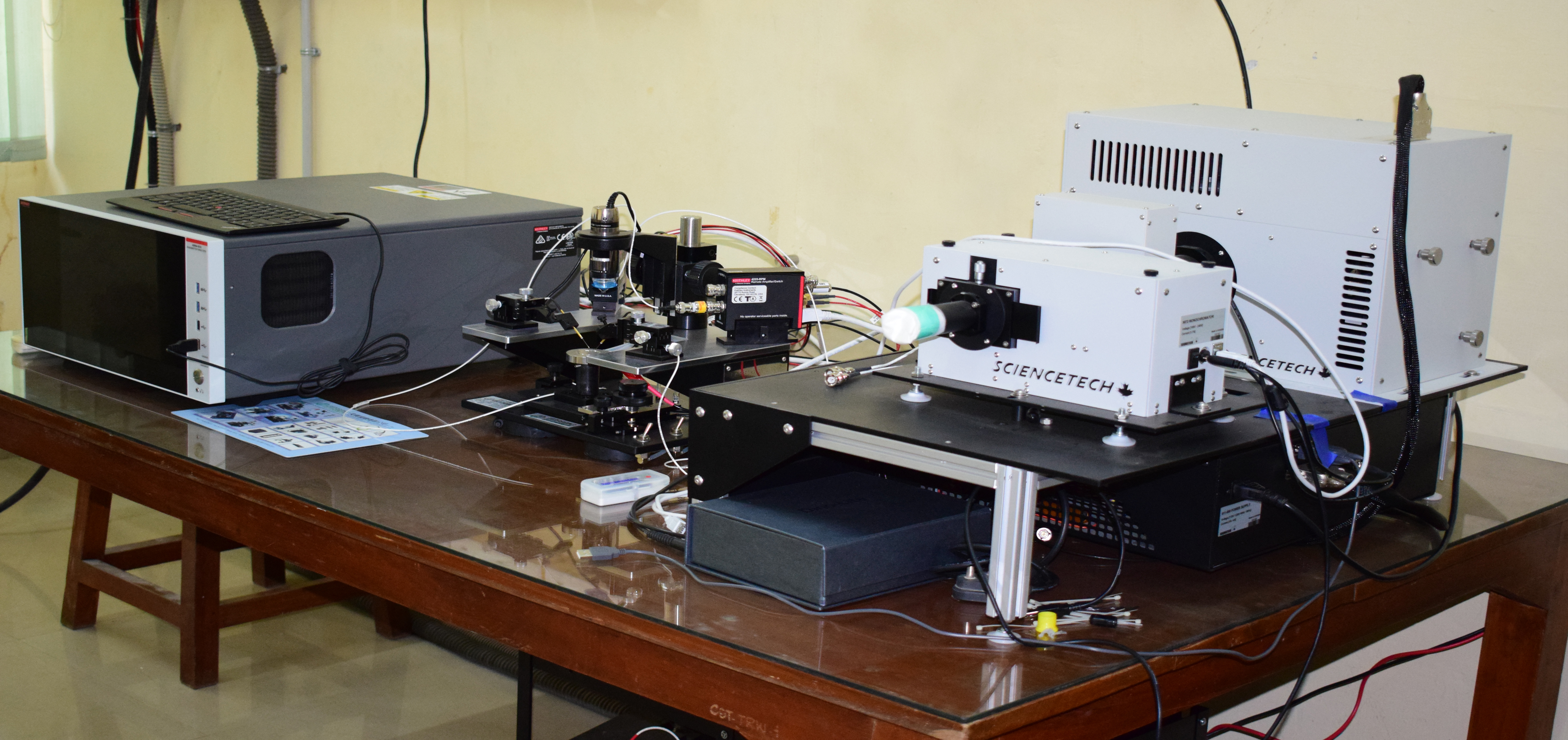
Integrated IPCE (Incident photon to current efficiency)
- The system consists of the following:
- Solar Simulator
- IV Measurement system
- QE measurement system
- Specifications:
- Solar Simulator
- Light source: continuous steady 500 W xenon light source (ozone-free).
- Maximum illuminated area: 100 mm x 100 mm (vertical illumination).
- Simulator is a class AAA (according to IEC & ASTM E 927).
- Lamp shutter can be operated by both manually and automatically.
- Light isolation box for sample loading and unloading.
- I-V measurement:
- Voltage range: 0.4 millivolt to 40 V (resolution < 400 µV).
- Current range: 0.2 microampere to 4A (resolution ≤ 200 nA).
- I-V measurement is fully automated.
- Quantum efficiency inbuilt in the system:
- System able to determine external quantum efficiencies.
- Additional lamp and optics for spectral illumination.
- Consisting of grating monochromator
- Source wavelength: 300 – 1800 nm with resolution: 0.5 nm and step size: 0.1 nm.
- Rotating wheel-based optical chopper with frequency Range 1-1000 Hz.
- Sample holder:
- Solid brass sample holder is compatible with different sample sizes of 20 x 20 mm², 30 x 30 mm², 40 x 40 mm², 50 x 50 mm², and 100 x 100 mm² solar Cells.
- One probe tip for voltage sensing in center (needle type).
- One spring loaded temperature sensor (PT100).
- Current can be drawn via entire sample holder surface or one single probe tip.
- Separate vacuum channels for each cell size.
- Sample holder has temperature variation in the range of 10 – 50 oC.
- Temperature instability: < ± 0.1°C
- Integrated vacuum pump for vacuum fixation of samples.
- Contact mechanism:
- 2 x Micropositioner with magnetic base and adjustable extension.
- Adjustable probe tip height / contact pressure.
- Equipped with Accuprobe Kelvin probes tips enabling 4 - point contact.
DATA NOT FOUND
PARAMETER ANALYZER
The semiconductor parameter analyzer (device analyzer) is used to integrate multiple measurement and performs the current‐voltage (I-V) and capacitance measurement (C-V (capacitance‐ voltage), C‐f (capacitance-frequency), and C‐t (capacitance-time) measurements accurately. It is used for I-V and C-V characterizations of various materials, devices and electronics widely because of its superior performance, powerful capabilities and ease of use.
- The Model 4200A-SCS Parameter Analyzer performs laboratory-grade DC, I-V, C-V, and pulse device characterization, real-time plotting, and analysis with high precision
- Its touchscreen interface accelerates and simplifies the process of taking data, so users can begin analyzing their results sooner
- Work more productively by acquiring data, analyzing plots, and printing reports simultaneously
- Sample tests and projects for a variety of applications are included to simplify startup
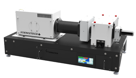
LIGHT SOURCE (SCIENCETECH: TLS-72-X500 MODEL
- Target material: Metals, alloys, metal oxides, metal nitride.
- Collimated, condensed, or coupled output light options. Light can be coupled to any optical system (including fibers and fiber bundles)
- Adjustable optical resolution from 20 nm down to 0.2 nm
- Flexibility of optional features: full automation, various sources and monochromators and more